Eurocode Settings
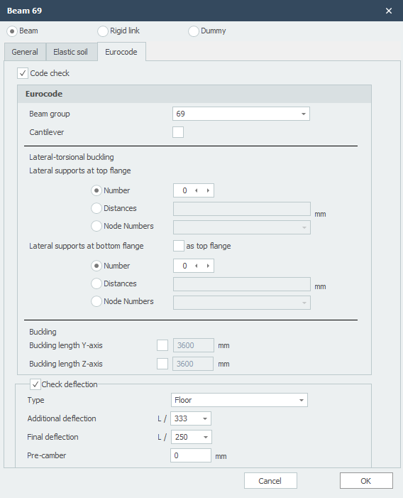
EN 1993-1-1 / EN 1995-1-1
Specifically and only for the check according to Eurocode 3: EN 1993-1-1 respectively Eurocode 5: NEN-EN 1995-1-1 data can be inserted.
Beam Group
Specifically and only for the lateral-torsional buckling resistance check a beam group can be inserted here. XFEM4U automatically detects for which beams this qualifies. Only the beams which are connected by a fully fixed connection to this particular beam and have the same profile will be showed. You can select which beams should be taken into account. For this group you subsequently enter the length between the lateral restraints and the buckling length out of plane.
Lateral Torsional Buckling
Amount of Lateral Supports / Distances Between Lateral Supports
This is only relevant for the check of lateral torsional buckling. You can enter the lateral supports for the top and the bottom flange.
There are 3 possibilities:
-
Number: The amount of lateral supports. That are the extra (lateral supports) between the supports distributed over the length of the beam(group).
-
Distances: The lengths between the lateral restraints from the beginning of the beam (group). The syntax is 'length1 length2 amountxlength3.. etc'. For example 3000 3x2200 2800
-
Node numbers: Selecting the node numbers which are in the beam group.
Buckling Lengths Y-axis and Z-axis
The check according to Eurocode 3: EN 1993-1-1 is based on a geometric non linear analysis. This means that the buckling of the beams is provided implicit in the analysis. For every load combination the internal stability is determined iteratively. By default the buckling length around the y-axis is equal to the beam length. The buckling length around the z-axis is equal to the biggest lateral torsional buckling length. You can also enter different values for both the buckling lengths.
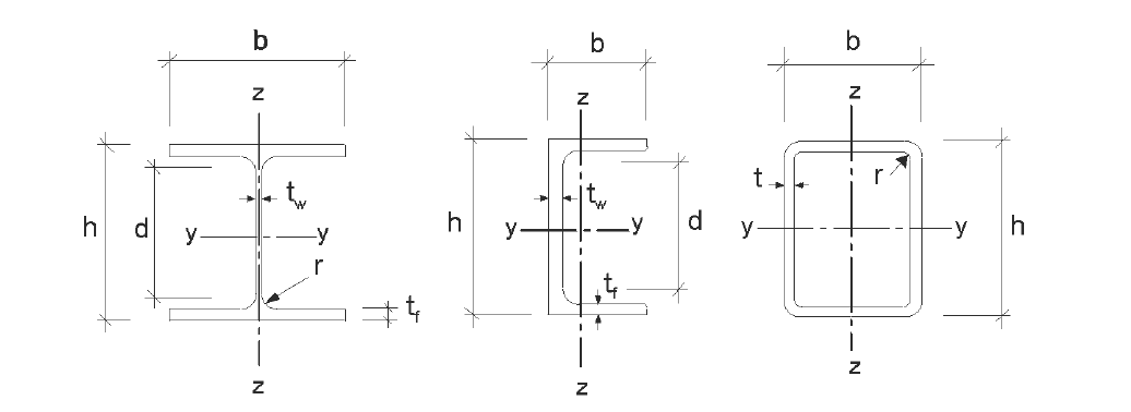
Note: Regardless of whether the profile is rotated with respect to the local coordinate system, the Y axis is the strong axis and the Z axis is the weak axis analogous to the Eurocode. (See below.) In all checks, all beam forces are transformed to this coordinate system.
Deflection Check
Check Deflection
Setting if deflection has to be checked.
Type
This influences the requirement of additional deflection.
Additional Deflection
Requirement of additional deflection.
Final Deflection
Requirements of final deflection.
Pre-camber
The size of pre-camber in mm.