General
By double-clicking on a plate (or 1 click right mouse button > Properties) the dialog box below becomes visible.
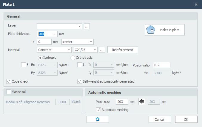
Layer
Beams can optionally be drawn in layers. This corresponds to the functionality of AutoCAD. The layers can be set visible or invisible (on/off). You can adapt the names of the layers. See Display options
Plate Thickness
The plate thickness in mm.
z
With this the slab is orientated relative to the schematic surface.
z is the distance in the local z-direction between the schematic surface and the reference line of the slab. The reference line of the slab is showed in the middle by default, but can be set at the top, middle or bottom.
Material
There is a choice of steel, concrete and wood (and otherwise).
Depending on the choice, the dialog box is customized to the different material data.
Isotropic / Orthotropic
By default, the plate is isotropic where the E and I around the x-axis and y-axis are equal. You can also enter the plate orthotropically where E and I are unequal about the x-axis and y-axis.
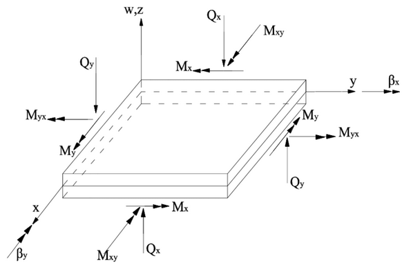
Note! The Ix and Ex, respectively, refer to the stiffness about the x-axis. The moment mxx is the moment that gives stresses in the x-direction. This sometimes causes confusion.
Ex / Ey
Elasticity modulus in N/mm2. This value is determined automatically but can be adjusted.
Ix / Iy
Moment of inertia mm4. This value is determined automatically but can be adjusted.
Poison Ratio
The poison ratio.
Holes in Plate

This enables you enter holes in a plate. See Holes in plate
Elastic Soil
This enables you to enter a elastic supported foundation slab. The elastic soil is schematized as a number of springs that can support positive reactions only. Possible "loosening" is therefore provided. The modulus of Sub-Grade Reaction constant is automatically converted to springs with the correct spring value.
Modulus of Sub-Grade Reaction
The modulus of Sub-Grade Reaction in kN/m3.
Global values of Sub-Grade Reaction of several types of soil:
| Type | Modulus Sub-Grade [kN/m3] |
|---|---|
| well-graded gravel and gravel / sand mixtures, with little or no fine | 80000 - 130000 |
| poorly graded gravel, with little or no fine | 80000 - 130000 |
| gravel / sand / clay mixtures | 50000 - 130000 |
| well-graded sand and gravely sand, with little or no fine | 50000 - 100000 |
| poorly graded sand, with little or no fine | 40000 - 100000 |
| sand / clay mixtures | 30000 - 80000 |
| very fine sand, loamy sand | 30000 - 50000 |
| solid clay | 10000 - 30000 |
| weak clay and peat | 0 - 10000 |
Mesh Size
The dimension of plate elements. The standard (recommended) mesh size is automatically determined but can be adjusted.
Automatic Meshing
When inserting a plate or wall, the plate or wall is automatically meshed. With small models, this is certainly convenient. Not so with large models. Meshing many connecting plates takes a relatively long time. You can disable automatic meshing. You can do that in the display options and here in the plate dialog. Now you can enter your plates even easier. And when you are done with that, you can mesh the plates at once.
Mesh
Button that re-generates the mesh.
Local Coordinate System
The x-axis of the local coordinate system of the plane load runs from the first point to the second point. With the display option Axis system plate you can make the local axes system of the plate visible. See Display options.
Invert Contour Direction

This function allows you to invert the direction of the contour line ("polyline"). By doing so you also influence the coordinate system of the plate.