Plate Edge
Plate edges are drawn as transparent tubes. By double-clicking on a plate edge (or 1 click right mouse button > Properties) the dialog box below becomes visible.
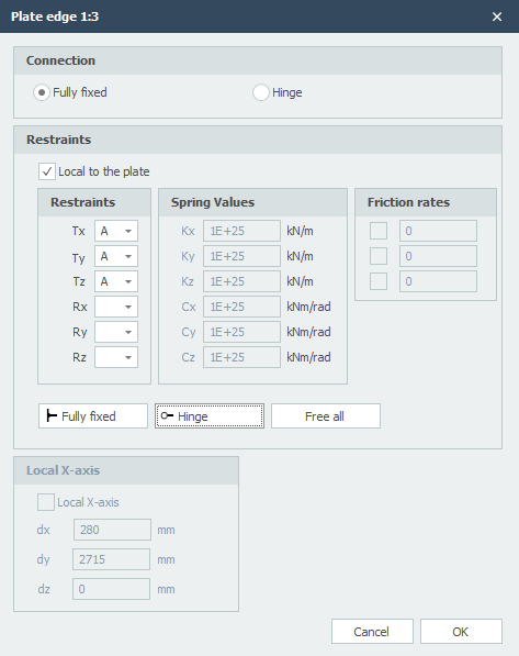
Connection
Setting whether plate edge elements are fully fixed connected or hinged.
Local to the Plate
Setting whether the supports are to be introduced in relation to the local axle system of the plate.
Supports / Restraints
Here you enter how the plate edge is supported. There are many possibilities.
You can use the most common / standard supports:
Fully fixed: Tx=A(Absolute), Ty=A, Tz=A, Rx=A, Ry=A, Rz=A. (That is the default setting)
Hinged: Tx=A, Ty=A, Tz=A. No moments can be transmitted, only transverse and normal forces.
Spring Support
You can also enter a spring support. Tx=S(Spring), Ry=S and/or Rz=S. You also give the spring value Kx, Cy and/or Cz in kN/m or kNm/rad.