Beams / Rigid Links
In the graphical screen beams can be added very easily by drawing them. Select this item in the function bar: 
Beams are drawn as a 'polyline' just as you know it from AutoCAD. The begin node from a following beam is the end node of the last drawn beam.
It is possible, but not necessary, to draw nodes before you insert the beams. You can also start with drawing the beams; in this way the nodes will be inserted automatically.
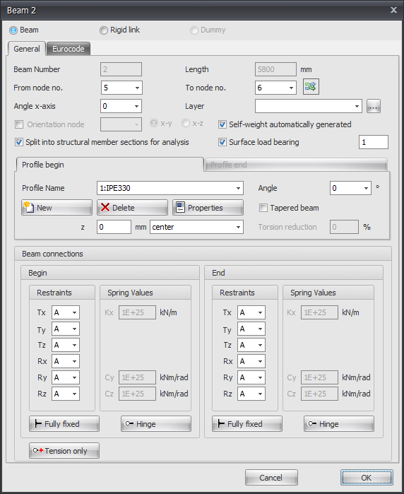
When you draw your first beam, the dialog box shown below appears. In this box you can, among other things, insert the beam connections and the profile of the beam. Use the escape-key or click the right mouse button to end the drawing of the beams.
Drawing Beams
As you are drawing a beam, help lines (horizontal and vertical) will appear connected to the previously inserted nodes. Often the node, to which you want to draw the beam, has the same x- or y- or z-value as the previous one. In this way it is easy to insert nodes. Obviously you can adapt the coordinates afterwards numerically or by moving the node.
While drawing a new beam, a dimension line parallel to the beam in one of the main directions x, y or z will appear. You can, just as you know it from AutoCAD, immediately insert the distances numerically by entering the value/values from your keyboard. There are 3 possibilities for drawing a beam:
1. Drawing a Beam with a Known Length in One of the Main Directions
The value will appear in the dimension line. Here you can type in the distance. By use of the enter-key the input is closed and the beam with that length will be added.
2. Drawing a Beam Using Relative Cartesian Coordinates (dx, dy, dz)
First you enter the distance in x-direction. The value will appear in the dimension line. Thereafter you type a semicolon ";" and the distance in y-direction. The value will appear in a second input field. Next you type a semicolon ";" and the distance in z-direction. The value will appear in a third input field. By use of the enter-key the input is closed and the beam is added.
3. Input of Relative or Absolute Cartesian Coordinates
Press the space key and the dialog box below appears. Here you can enter relative coordinates or absolute coordinates directly.
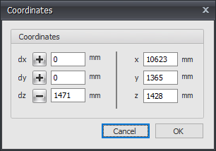
In this way, you can quickly insert your construction.
Profile Selection
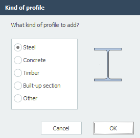
When you draw a beam for the first time, a profile needs to be chosen/inserted. There is asked what kind of profile you want to add. Also when you insert a new profile, there is asked which kind of profile you want to add.
Subsequently the following dialog box of the profiles is shown. See Profiles
Changing a Beam
Changing a beam is possible by clicking on the beam with the left mouse button, and subsequently choose properties by clicking with the right mouse button. There is an easier way, namely a double click on the beam. Consequently the following dialog box will be opened.