Nodes
Nodes can easily be added in the graphical screen. To do this, you have to choose  in the menu bar. In this mode you can add multiple nodes by means of the left mouse button. By placing the node, you will see the coordinates in the right bottom, as shown in this image below.

Nodes can be added arbitrarily in a fixed raster or at grid lines.
Supports are nodes which are restrained in a certain direction.
Changing a Node
Changing a node is possible by clicking on the node with the left mouse button, and subsequently choose properties by clicking the right button. There is an easier way, namely a double click on the node. Consequently the following dialog box will be opened.
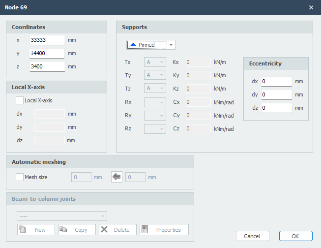
Coordinates
x
x-coordinate
y
y-coordinate
z
z-coordinate
Local x-axis
Supports
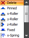
See Supports
These are the supports that are most common in practice, but you can also add an arbitrary (spring) support by making use of 'A', 'P', 'N' or 'S'.
Eccentricities
Only for supports (nodes with restrictions/restraints in a certain direction) you can add an eccentricity by inserting 3 relative coordinates dx, dy and dz. An extra node and a 'stiff' beam are automatically generated. Hereby you can, for example, in the calculation of a concrete beam grid, take the misplacement of a pile into account. The foundation beams can subsequently be tested for torsion and extra bending.
Mesh
See Mesh
Beam-to-Column Joints
See Node joints
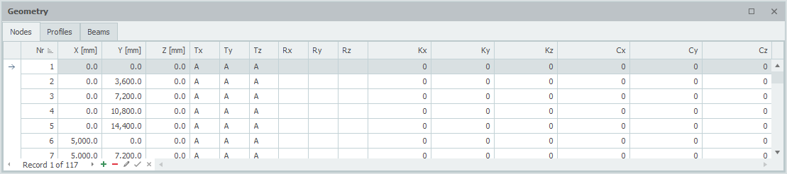
Table Nodes
Nodes can also be added/changed in the bottom left table Nodes. It does not matter. It is also possible to change between graphical input and numerical input via tables.