Display Options
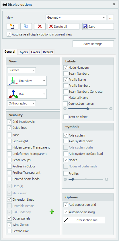
Views
Optional an unlimited number of views can be made. The camera position and all display settings will be stored per view. All views are also saved in the project file (input file) so that they can be displayed and/or included in the output again when the project is reopened. You can of course rename all views. In the output selection you can select the views to be included in the output. All 3D view images of Geometry/Loads and Results are automatically placed in the right place. When generating output all selected 3D view images are also saved as a PNG-file in the subfolder "XFEM4U_Images" where the project file (input file) is saved.
View
You can change the view. Name of the view can be adjusted here.

A separate dialog box is displayed where you can change the order of all created views.

Add a new view. The default name is "View 1", "View 2", ... and so on.

Copy active view.

Delete active view.

Delete all views.
Save/Update the actual camera position of the current view. When you change the camera position you need to save this. All display settings are automatically saved in the current view.
Auto Save All Display Options in Current View
Setting whether all view options should be automatically saved in the view.
View Settings
Mesh / Surface

Setting whether a mesh or surfaces need to be drawn.
Line View / Solid
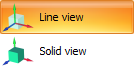
Setting whether: - The wireframe and nodes are drawn (Line view) or that - All profiles are drawn as solid model in true size (Solid model view)
Views

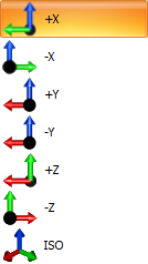
You can change the view. Default is ISO (isometric view).
This list also automatically contains all grids and levels. The depth is not (yet) adjustable and is now 500mm in front and 500mm behind. Only the objects within these distances will be visible.

With the setting perspective/orthographic you can set if you want the view to be in perspective.
Grid Lines / Levels
Grid lines, levels and/or help lines will be drawn. See Gridlines/levels.
Base
Setting whether the base needs to be drawn.
Self-weight
Setting whether the automatically generated beam loads as a consequence of the self weight need to be drawn in the load case permanent.
Hidden Layers Transparent
When some layers are set to be invisible, the beams in these layers are not drawn anymore. With this setting the beams in the invisible layer can be drawn transparent. This is very convenient for giving presentations.
Undeformed Transparent
Setting when drawing the deformed construction (tab Result: deflection), the undeformed construction needs to be drawn transparent.
Beam Groups
Beam groups that are created (See Eurocode) can be graphically displayed. Also the lateral supports at the top and bottom flange are displayed.
Profiles in Colour
The different profiles can be drawn in a colour. Every profile has its own color. By this it can be easily checked if all the profiles are inserted right.
Profiles Transparent
Only in Line view: The profiles are drawn transparent, as solids.
Show Derived Beam Loads
Using surface loads all beam loads will be generated automatically. You can display all derived beam loads.
Plate(s)
Setting whether plate(s) need to be drawn.
Plate Mesh
Setting whether the plate mesh need to be drawn.
Dimension Lines
Setting whether the dimension lines need to be drawn.
Unstable Beams
Setting whether the unstable beams need to be drawn.
DXF Underlay
You can import a DXF-underlay which will help you entering your construction. Setting whether this DXF underlay needs to be drawn.
Outer Panels
Setting whether the outer panels need to be drawn.
Wind Zones
When using the load generator a setting whether the wind zones need to be drawn.
Section Box
Section Box as in AutoCAD Revit, you can use a Section Box to limit the visibility of the model. The objects of the model inside the section box are still visible, what is outside it is no longer visible. So this allows you to view parts of your construction but it also allows you to reduce your work area as well.
Tip: Use Section Box. You will experience that it is convenient and very efficient.
Add Support on Grid
When drawing a beam, a pinned support is automatically generated when the node is at a grid point.
Automatic Meshing
When inserting a plate or wall, the plate or wall is automatically meshed. With small models, this is certainly convenient. Not so with large models. Meshing many connecting plates takes a relatively long time. You can disable automatic meshing. You can do that here in the display options and in the plate dialog. Now you can enter your plates even easier. And when you are done with that, you can mesh the plates at once.
Intersection Line
You can draw an intersection line within a plate. This will enable you to show forces in this section. See tab Results.
Labels
Node Numbers
The node numbers are displayed between brackets (..) at the node.
Beam Numbers
The beam numbers are displayed at the beam.
Profile Names
The profile names are displayed at the beam.
Profile Numbers
The profile numbers are displayed at the beam.
Material Name
The material names are displayed at the beam.
Text on White
Setting whether all the text values are displayed on a white background. By default this function is turned off.
The scale of the text can be set.
Symbols
Axis
Setting whether the global coordinate system should be drawn.
Axis System Beam
The local coordinate system will be drawn in the middle of the beam. This is important for inserting the beam loads which are entered in the local beam coordinate system. See Beam loads.
Axis System Plate
The local coordinate system will be drawn. See Slabs.
Axis System Surface Load
View the local coordinate system of the entered surface loads.
Nodes
Only in Line view: Setting whether the nodes should be drawn as dots.
Profiles
Only in Line view: Setting whether a little part of the profile should be drawn in the middle of schematic line of the beam.
The scale of the symbols can be set.
Layers
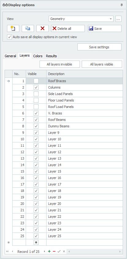
Layers
The layer function works the same as in AutoCAD. Beams can be placed in one or multiple layers. See Beams. The layers can be visible or not. Layers can be renamed.
By making smart use of this functionality you can make the graphical input easier and you will keep overview. Also for giving a 3D presentation, the layers are very convenient.
Tip: Use layers. You will experience that it is convenient and very efficient.
The  and
and  buttons allow you to work faster. For example, do you want to see a layer? Then turn off all layers and then turn on the corresponding layer.
Colors
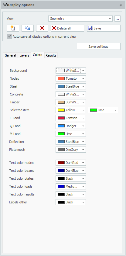
Colors
Here the colors of the different parts can be set.
Results
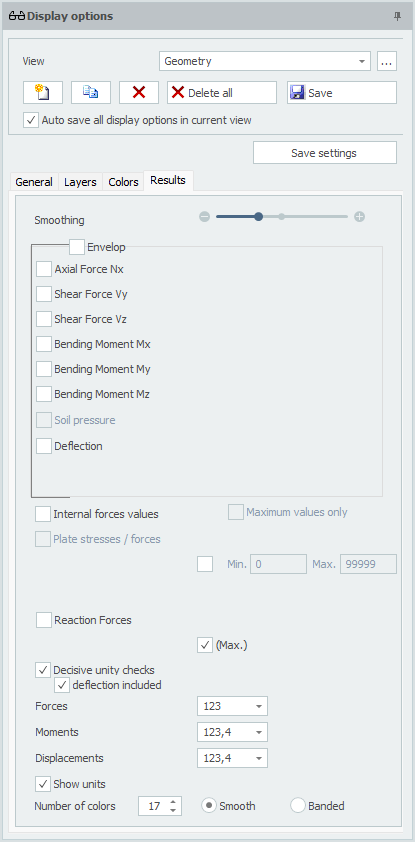
Smoothing
With the display of the N-, V- and M-lines and the deformations, the beam is divided into multiple beam parts. This amount can vary between minimal 3 parts to a maximum of 30 parts. By default this value is set to 10.
Envelope
Allows you to display envelope Nx-, Vy-, Vz-, Mx-, My-, Mz- and deformation lines.
Axial Force Nx
Drawing of the Nx-line. The scale can be set.
Shear Force Vy
Drawing of the Vy-line. The scale can be set.
Shear Force Vz
Drawing of the Vz-line. The scale can be set.
Bending Moment Mx
Drawing of the Mx-line. The scale can be set.
Bending Moment My
Drawing of the My-line. The scale can be set.
Bending Moment Mz
Drawing of the Mz-line. The scale can be set.
Deflection
Drawing of the deflection line. The scale can be set.
Internal Forces Values
Setting whether forces should be displayed numerically.
Maximum Values Only
Only the absolute largest values are displayed. Allows the number of texts on image to be reduced.
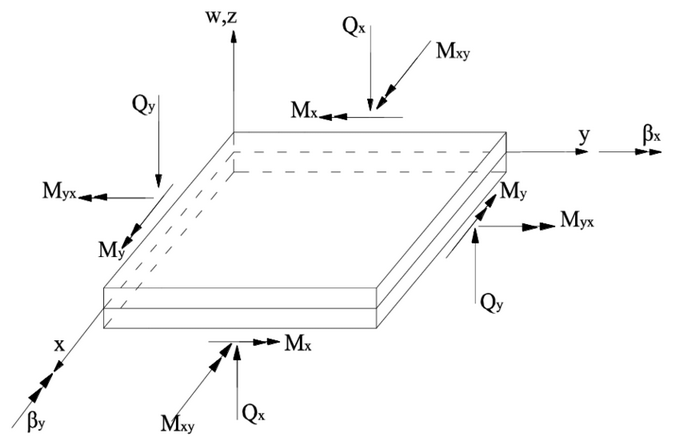
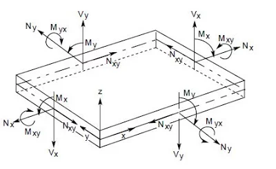
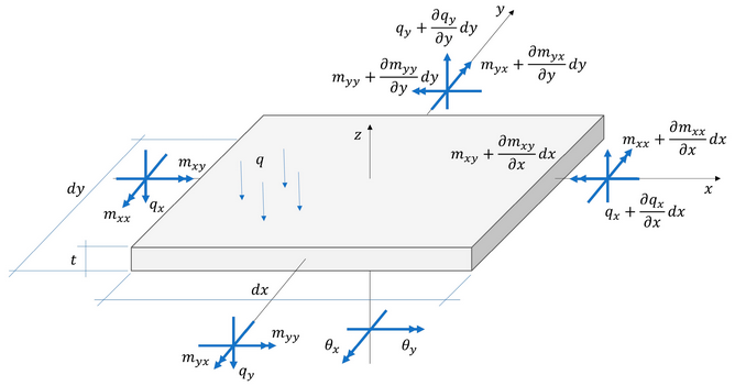
Plate Stresses / Forces
Drawing of the plate stresses and forces in colour. A colour scale appears on the left. It can be set which stress or force is to be displayed. Stresses can be displayed as membrane, bending or combined.
| Key | Description |
|---|---|
| s-x | Stress in x-direction |
| s-y | Stress in y-direction |
| t-xy | Shear stress |
| s-von Mises | Composed von Mises stress |
| nxx | Membrane force in x-direction |
| nyy | Membrane force in y-direction |
| nxy | Shear force in xy-direction |
| mxx | Moment that causes stresses in x-direction |
| myy | Moment that causes stresses in y-direction |
| mxy | Torsional moment |
| vx | Shear force |
| vy | Shear force |
| Mudx | Wood and Armer |
| M'udx | Wood and Armer |
| Mudy | Wood and Armer |
| M'udy | Wood and Armer |
| Asxb | Required reinforcement in x-direction on bottom side |
| Asxt | Required reinforcement in x-direction on top side |
| Asyb | Required reinforcement in y-direction on bottom side |
| Asyt | Required reinforcement in y-direction on top side |
| Asxb_extra | Required extra reinforcement on basic reinforcement in x-direction on bottom side |
| Asxt_extra | Required extra reinforcement on basic reinforcement in x-direction on top side |
| Asyb_extra | Required extra reinforcement on basic reinforcement in y-direction on bottom side |
| Asyt_extra | Required extra reinforcement on basic reinforcement in y-direction on top side |
| Asw | Required shear reinforcement (vertical stirrup reinforcement) |
| m1 | Principal moment m1 |
| m2 | Principal moment m2 |
| v0 | Maximum shear force v0 |
| Traj-m | Moment lines |
| Traj-v | Shear force lines |
| Soil pressure | Soil pressure in case of slab foundation |
3D Isosurfaces
Display the plate stresses and forces three-dimensionally.
Intersection Line
Drawing of section forces Mnn, Mtt, Mnt, Vn, Vt, Nnn, Ntt or Nnt.
Reaction Forces
Drawing of the reaction forces in all the supports. It can be set which directions need to be drawn. By default all the directions x, y and z are drawn.
Decisive Unity Checks
Per beam the unity checks can be displayed. These are results from the check according to the Eurocode (steel). When the unity check is less than 1.00 the beam meets the criteria, and a green dot is drawn  . When the unity check is greater than 1.00 the beam does not meet the criteria and a red triangle
  is drawn.
Note: When you double click on the dot/triangle, a detailed calculation of the concerning beam is shown.
Min.Max.
Minimum and maximum value of the unity check. Only beams with a unity check that lie between the minimum and maximum value are represented graphically.
Forces / Moments / Displacements

It can be set how many decimals should be displayed.