General
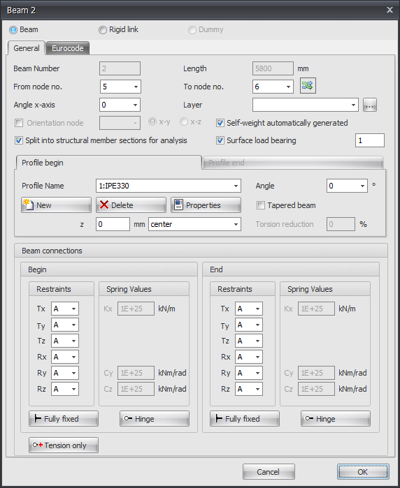
Beam Number
The number of the beam.
Length
The length of the beam in mm.
From Node No.
The number of the begin node.
To Node No.
The number of the end node.
Flip Beam Orientation

By the use of this function, you can turn around the beam orientation. The begin- and end node will be switched.
Angle x-axis
The angle in which the local coordinate system can rotate around the x-axis.
The clockwise direction is positive.
Layer
Beams can optionally be drawn in layers. This corresponds to the functionality of AutoCAD. The layers can be set visible or invisible (on/off). You can adapt the names of the layers. See Display options
Orientation Node
The number of the orientation node. This is a node in the local x-y plane or in the x-z plane.
Split into Structural Member Sections for Analysis
Setting if for analysis the beam has to be split into several partial beams when nodes are found on the beam. This function is enabled by default.
Automatically Generate Dead Weight of the Beam
Setting whether the dead weight of the beam needs to be generated. This function is enabled by default.
Surface Load Bearing
Setting whether the beam carries the surface load or not. Also a correction factor by which the beam loads generated from the surface loads are increased or decreased, respectively, to account for the static indeterminacy of the imposed plate. See Surface loads.
Profile Name
Here you choose the profile type.
Angle
The angle of the profile. That is the angle relative to the local coordinate system. Normally this is zero degrees. When you want to for example enter the column rotated (so loaded at its weak axis) you fill in 90 degrees.
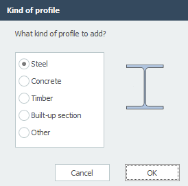
Profile Management


You can also add new profiles and delete profiles. Choose for Properties when you want to adapt the profile data and/or want to select another standard profile type from the profile database.
With every new profile, there is asked what kind of profile you want to add.
Tapered Beam
You can optionally enter a tapered beam (Non-prismatic beam). The tab "Profile end" is activated. Here you can enter the 2nd profile at the end of the beam. Attention! The basic shape of the profile section (H-, U-, L-shape, etc.) must match that of the profile at the beginning of the beam.
For calculation background.
z
With this the profile is orientated relative to the schematic line. (The schematic line is the line from the begin node to the end node)
z is the distance in the local z-direction between the schematic line and the reference line of the profile. The reference line of the profile is showed in the middle by default, but can be set at the top, middle or bottom.
Torsion Reduction
Percentage by which the torsion stiffness of the beam is reduced. Specifically for concrete beam grids, it is allowed to reduce the torsion stiffness in case of compatibility torsion. Thereby the occurring torsion moment is lower, and less torsion reinforcement is needed. (stirrups and longitudinal reinforcement)
Beam Connection Begin and End
Here you enter how the beam is connected at the begin node and at the end node. There are multiple options.
You can make use of the most common / standard connections:
Fully Fixed
Tx=A(Absolute), Ty=A, Tz=A, Rx=A, Ry=A, Rz=A. (That is the standard setting)
Hinge
Tx=A, Ty=A, Tz=A. There is no transfer possible between moments, only shear force and normal force.
Tension Only
This works the same as a hinge support, the only difference is that tensile forces (positive normal forces) can be transferred.
Springer Connection
You can also add a beam with a springer connection. Tx=S(Spring), Ry=S en/of Rz=S. You also need to insert the spring constant Kx, Cy and/or Cz in kN/m resp. kNm/rad
Input Per Beam
This gives you the possibility to adapt the input for every new beam.