Surface Loads

Surface loads can be used for plates, walls and beam structures. In the case of beam structures, all beam loads are generated automatically. However, there are some important ground rules here. Look at Ground rules surface loads.
 Watch the demo.
You can draw any surface as a 'polyline' just as you know it from AutoCAD. Press the escape-key or click the right mouse button when finished.
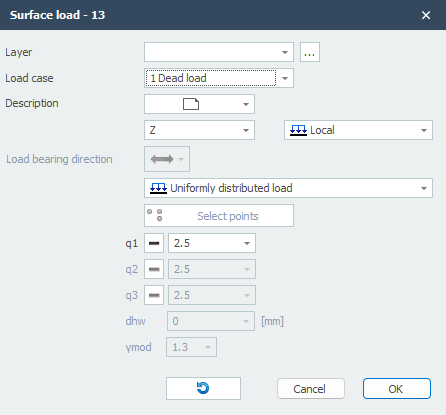
Next the dialog box shown below is opened.
Pay attention! To be able to generate beam loads, edge beams must occur.
With the display option Show derived bar loads you can display all automatically generated beam loads. You can use this to check whether the loads have been created correctly. See Display Options.
Load Case
Choice for the load case.
Description
Free text to describe the load.
Direction of the Load / Local-Global
The load can be inserted in 3 directions. In x-, y- or z-direction relative to the local coordinate system (standard) or the global coordinate system.
You can choose "Local", "Global" and "Global projective".

When choosing Global projective (for snow and live loads) the load is related on the projection area.
q1 [,q2 and q3]
The magnitude of the load in kN/m2.
Load Bearing Direction
Here you can enter the load bearing direction of the plate you will using. There are 3 options.

Type of Load
Here you can specify whether the load is uniformly distributed or linear. With a linear running load you can enter, for example, a water pressure or soil pressure on a wall. Or a running wind load over a tall building.

Linear loads are defined by specifying loads q1, q2 and q3 in 3 points. By default, the first 3 points of the contour line are selected. Of course, you can still optionally select other points. The button below allows you to select other 3 points of the "polyline".

The x-axis of the local coordinate system of the plane load runs from the first point to the second point. With the display option Axis system surface load you can make the local axes system of the surface load visible. See Display options.
Invert Contour Direction

This function allows you to invert the direction of the contour line ("polyline"). By doing so you also influence the coordinate system of the surface load.