Node Displacements (Forced Node Displacements)

The dialog box shown below is opened.
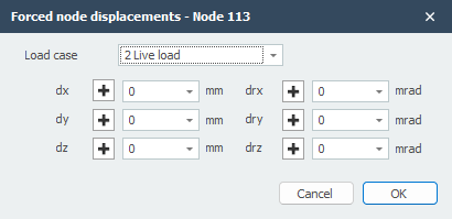
Load Case
Option for the load case.
Displacement Input
The node displacement will be inserted in the global coordinate system. When for a particular node, a local coordinate system is inserted, the displacement will be inserted relative to this coordinate system.
dx
The amplitude of the displacement in mm in the x-direction
dy
The amplitude of the displacement in mm in the y-direction
dz
The amplitude of the displacement in mm in the z-direction
drx
The amplitude of the rotation in mrad around the x-axis
dry
The amplitude of the rotation in mrad around the y-axis
drz
The amplitude of the rotation in mrad around the z-axis
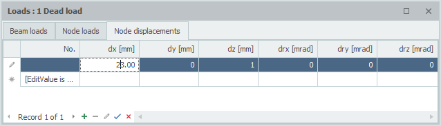
Table
Node displacements can also be added/changed in a table. It does not matter. It is also possible to change in between graphical input and numerical input via tables.