Node Loads

The dialog box shown below is opened.
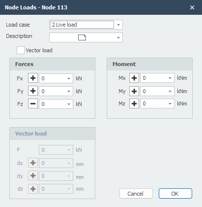
Load Case
Option for the load case.
Load Input
The node load will be inserted in the global coordinate system. When for the particular node, a local coordinate system is inserted, the forces will be inserted relative to this coordinate system.
Description
Free text to describe the load.
Fx
The magnitude of the force in kN in the x-direction
Fy
The magnitude of the force in kN in the y-direction
Fz
The magnitude of the force in kN in the z-direction
Mx
The magnitude of the moment in kNm around the x-axis.
My
The magnitude of the moment in kNm around the y-axis.
Mz
The magnitude of the moment in kNm around the z-axis.
Vector Load
An opportunity for entering the load as a vector in a certain direction.
F
The magnitude of the vector force in kN
dx
Relative distance in x-direction
dy
Relative distance in y-direction
dz
Relative distance in z-direction
By the use of dx, dy and dz the direction of the vector force is determined.
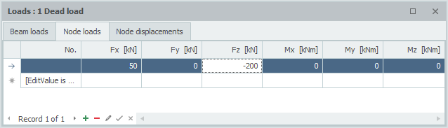
Table
Node loads can also be added/changed in a table. It does not matter. It is also possible to change in between graphical input and numerical input via tables.