Menu
Renumber

With these function the nodes and beams will be renumbered.
Undo and Redo
 Undo (Ctrl+Z)
  Redo (Ctrl+Y)
Every adaptation can be reversed and repeated without limitation. Do you want to go back to a previous situation? That is possible. The undo function will help you flawless and fast.
A wrong or accidental input can be restored but with this function you can also quickly compare different solutions. It helps you make an optimal design of your construction.
 Look at the demo
Copy
 Copy
Copy
With this function you can easily copy selected nodes, beams and plates. You select the concerning nodes and beams by the use of the 'select window / crossing'. See Make selections. Thereafter you mark the beginning by clicking on the screen. (1. Select base point.) Now move the mouse in the direction in which you want to copy the nodes and beams. (2. Select second point in the direction you wish to copy.) Just like the situation within AutoCAD, a dimension line is visible. You can also directly insert the distance via your keyboard. You close with the Enter-key. All nodes, beams and plates will be relatively copied.
The COPY command is repeated. So you can place your copy in several places and thus enter your model even faster and easier. Use the esc-key or the right mouse button to end the copying process.
Move
 Move
Move
With this function you can easily move nodes. You select the concerning nodes by the use of the 'select window / crossing'. See Make selections. Thereafter you mark the beginning by clicking on the screen. (1. Select base point.) Now move the mouse in the direction in which you want to move the node. (2. Select second point in the direction you wish to move.)
While moving your mouse, a dimension line in one of the main directions x, y or z will appear. You can, just as you know it from AutoCad, immediately insert the distances numerically by entering the value / values from your keyboard. There are 3 possibilities:
1. Move with a known length in one of the main directions
The value will appear in the dimension line. Here you can type in the distance. By the use of the enter-key the input is closed and the selected nodes will be moved.
2. Move using relative Cartesian coordinates (dx, dy, dz)
First you enter the distance in x-direction. The value will appear in the dimension line. Thereafter you type a semicolon ";" and the distance in y-direction. The value will appear in a second input field. Next you type a semicolon ";" and the distance in z-direction. The value will appear in a third input field. By the use of the enter-key the input is closed and the selected nodes will be moved.
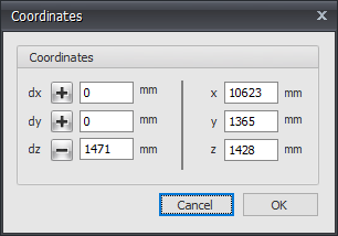
3. Move using relative Cartesian coordinates (dx, dy, dz) or to absolute Cartesian coordinates (x, y, z)
Press the space key and the dialog box below appears. Here you can enter relative coordinates or absolute coordinates directly.
Delete
 Delete
With this function you can easily delete parts. You select the concerning objects by using the 'select window / crossing'.
Rotate
 Rotate
With this function you can rotate selected parts. You can also make multiple copies with this function.
You select the concerning nodes and beams by the use of the 'select window / crossing'. See Make selections. Thereafter you select the first point of rotation axis. (1. Select first point of rotation axis.) Second you select the second point of the rotation axis. (2. Select second point of rotation axis.) The dialog below will be visible.
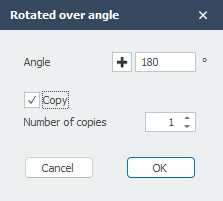
Enter the value of the rotation angle. Optional you can also make multiple copies.
Multiple Copies (Linear Arrays)
 Multiple Copies (Linear Arrays)
With this function you can easily make multiple copies of selected nodes, beams and plates. You select the concerning nodes, beams and plates using the 'select window / crossing'. See Make selections. Thereafter you mark the beginning by clicking on the screen. (1. Select base point.) Now move the mouse in the direction in which you want to copy the nodes and beams. (2. Select second point in the direction you wish to copy.) Just like the situation within AutoCAD, a dimension line is visible. You can also directly insert the distance via your keyboard. You close with the Enter-key. The dialog below will be visible.
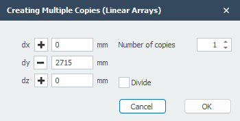
Enter the number of copies. With divide the copies will be distributed over the distance. All nodes and beams will be relatively copied.
Sub Menu
Flip
 Flip
Flip
With this function you can mirror or flip selected parts. The mirror surface is arbitrary and is selected with 3 points.
You select the concerning nodes and beams by the use of the 'select window / crossing'. See Make selections. Thereafter you select the mirror / flip surface by 3 points.
1. Select first point of mirror. 2. Select second point of mirror. 3. Select third (last) point of mirror.
The dialog below will be visible.
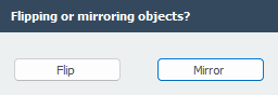
Choose to mirror or flip the selected objects.
Divide Beam
 Divide beam
With this function you can easily divide your selected beams into equal beam parts.
Determine Intersections of Beams
 Determine intersections of beams
With this function you can easily calculate the intersections of your selected beams. Nodes will be added on each intersection found.
Split Beams
![]() Split beams
Split beams
Beams can be split into multiple beams where all beam loads are also split. You select the beams(s)) and the node(s) on the beam and choose Split beams.
Merge Beam
![]() Merge beam
Merge beam
This is an inverse operation of Split beams.
Switch Beam Orientation
![]() Switch beam orientation
Switch beam orientation
With this function you can easily switch the begin and end node of your selected beams. By switching the nodes the direction of the local beam axis changes.
Make Beam Group
Make beam group
Specifically and only for the lateral-torsional buckling resistance check a beam group can be inserted here. XFEM4U automatically detects for which beams this qualifies. Only the beams which are connected by a fully fixed connection to this particular beam and have the same profile will be showed. You can select which beams should be taken into account. For this group you subsequently enter the length between the lateral restraints and the buckling length out of plane. See Eurocode.
Reversing Plate Contour
 Reversing plate contour
The direction of the plate contour also determines the direction of the local z axis. With this function you can reverse the direction of the plate contour.
Rotate About Local Z-axis
Rotate about local z-axis
The direction of the x-axis of the plate is equal to that of the 1st contour side. With this function, you can slip that 1st side and thus you can adjust the direction of the x-axis.
Generate Plate Load
Generate plate load
This function allows you to quickly set a surface load on the plate. The contour of the surface load is then also the contour of the plate.